
Hello everyone! First off, I need to mention that my background is in Computer Science (this project is actually for my thesis) and not in Electrical or Computer Engineering. As such, everything I’ve learned has been largely on my own, within the past few months.
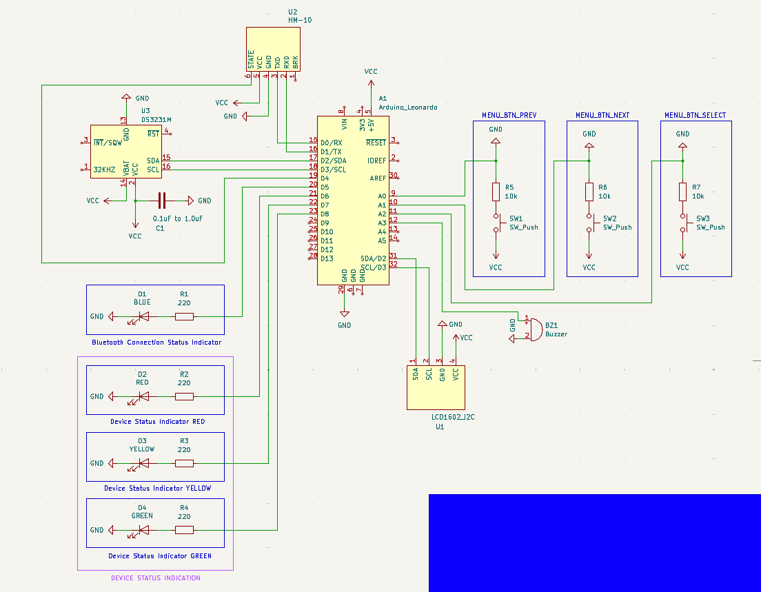
That being said, I would feel more confident if an experienced set of eyes could take a look at my schematic and let me know if anything pops out as wrong/bad practice. Furthermore, with regards to the decoupling capacitor on the DS3231M RTC module (C1 on the schematic) I have a question: Would there be any problem if I use an electrolytic capacitor instead of a ceramic one? I read some stuff about the topic and people recommend using ceramic capacitors most of the time (I think) but others say that there shouldn’t be a problem to use an electrolytic capacitor. I’m asking because I’ve already placed an order for parts, and one of them is this assorted set of electrolytic capacitors.
Please if you notice any mistakes or things that are not done the best way let me know, and try to explain why as simply as you can. As I said, I don’t have a background in EE, even though it highly interests me and I want to learn.
Here is the schematic:
Many thanks in advance!
Decoupling capacitor is there to filter out hogh frequency ripples from the lower supply. It is very hard for the consumer to know the high frequency current consumption of the chip, and its effects on the chip. Therefore decoupling is something where you should always follow the datasheet recommendation. As others said, ceramic capacitor has lower series resistance and inductance, which makes it the better choice for decoupling. Follow the instructions on layout as well, which usually says that decoupling capacitor should be as close as possible to the chip and grounded well. That being said, if you are prototyping on a breadboard, series inductance of a capacitor may not be your biggest concern, as breadboard connections will have that too. You can also still try to get your circuit working with the capacitor you have while waiting for ceramic one, chances are any capacitor will work good enough.
Yes, I’ll probably just be doing this on breadboards, but there is a chance I might eventually move it to a PCB (assuming I learn that part of KiCAD soon enough and have enough time to order PCBs before I need to submit). In either case, the power source of the entire system will probably be some holder/rack (not sure what they are actually called) for several AA or AAA batteries. Basically it will need to be something that a theoretical consumer would be able to replace easily - the batteries that is.
Do the problems outlined in your and other’s comments about these types of capacitors in this application also present from regular batteries, or are they usually not high voltage enough to cause problems?
It is not much about the voltage level but high frequency current activity. Current can cause voltage drop on parasitic resistance and inductance of the breadboard, jumpers, connections, passive components etc. and can cause supply of the chip to be non-ideal or ripple. Your power source is a battery and not a switching power supply, so power will be cleaner, which is good. The chip also doesn’t consume high current, and its output is 32khz clock, fairly low frequency. So I wouldn’t worry so much about decoupling.
As for the RTC’s 32kHz clock as you can see from my diagram I didn’t connect it to anything. I was under the impression that it was unnecessary for my purpose after looking at the datasheet. Am I wrong?