Hello everyone! First off, I need to mention that my background is in Computer Science (this project is actually for my thesis) and not in Electrical or Computer Engineering. As such, everything I’ve learned has been largely on my own, within the past few months.
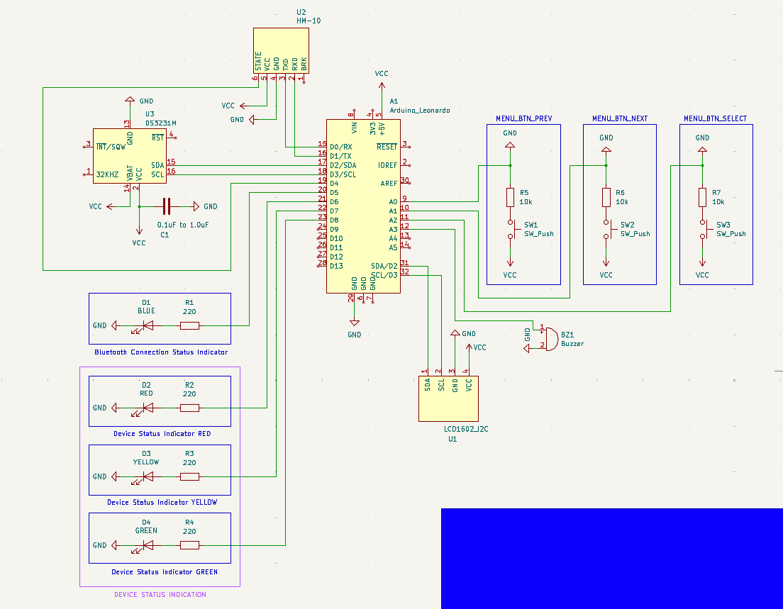
That being said, I would feel more confident if an experienced set of eyes could take a look at my schematic and let me know if anything pops out as wrong/bad practice. Furthermore, with regards to the decoupling capacitor on the DS3231M RTC module (C1 on the schematic) I have a question: Would there be any problem if I use an electrolytic capacitor instead of a ceramic one? I read some stuff about the topic and people recommend using ceramic capacitors most of the time (I think) but others say that there shouldn’t be a problem to use an electrolytic capacitor. I’m asking because I’ve already placed an order for parts, and one of them is this assorted set of electrolytic capacitors.
Please if you notice any mistakes or things that are not done the best way let me know, and try to explain why as simply as you can. As I said, I don’t have a background in EE, even though it highly interests me and I want to learn.
Here is the schematic:
Many thanks in advance!
Would there be any problem if I use an electrolytic capacitor instead of a ceramic one?
Electrolytics have much, much larger parasitic resistances. Or under more layman terms: Electrolytics are always “slower” than ceramic capacitors. However, you’re using a Arduino Leonardo, which as a 1uF ceramic capacitor across VCC / 5V and GND. You “might” get lucky and the capacitor there will save you. Its very far away and might not work though.
Capacitors are basically considered the most important and numerous component on modern electronics. You should basically spam them to increase your reliability. They’re a lucky-charm, many “mysterious” issues get solved with more capacitors, lol. Well, at least at the beginner levels.
Lots of 100nF capacitors (not too small, not too big) help out the majority of designs. Of course, an expert would run real power models and simulate the results. But a beginner should instead just place a 100nF capacitor next to every VCC-pin of every chip you use. Seriously.
I see. A new question arose from reading your reply. Theoretically, if I were to put e.g. 2x1uF electrolytic (or any type) capacitors basically in series next to the power source of a chip, does that increase reliability or is there little reward for it?
in series
In parallel. Remember that the parasitic resistance (and inductance) are the major issues.
Capacitance adds in parallel. Resistances / inductances half in parallel. So by putting in parallel the capacitance grows while resistance/inductance shrinks.
2x1uF electrolytic (or any type) capacitors basically in series next to the power source of a chip, does that increase reliability or is there little reward for it?
“It Depends”. For full details, seek a masters degree in power-electronics, PCB design, power delivery networks, and other advanced subjects.
You’re kinda-sorta on the right track but your understanding of the magnitudes at play here are way off.
https://www.we-online.com/components/products/datasheet/860020672005.pdf
This 1uF aluminum electrolytic capacitor from Wurth Electronics is measured to be 39.553 Ohms. With 2x of this capacitor in parallel you’ll have ~20Ohms (halved) and 2uF of capacitance. (parallel halves the resistance and doubles the capacitance). The 20% to 80% rise-time of RC-circuits can be calculated with just 1.4 * RC constant. This means your two-capacitor team “reacts” within 56 microseconds.
Meanwhile, the 1uF GRT033R60G105ME13 Murata 0201 (American) MLCC / Ceramic capacitor, commonly used for this task, has 0.01 ohms of resistance, roughly a THOUSAND-times less resistance than the Aluminum / Electrolytic capacitor. This capacitor “reacts” to the changing conditions within 0.014 microseconds (aka: 14 nanoseconds).
Do you see the difference? The name of the game is to get:
-
Enough capacitance to deal with the problem.
-
After that, minimize resistance as low as possible (and inductance for the “worst” cases, like those 300W GPU we shove into computers), so that the capacitor can actually “react” in time.
Once you “have enough capacitance” (and for most chips, that is 100nF), the way you speed up capacitors is buying low-resistance capacitors. And aluminum is among the slowest / biggest resistance capacitors in the entire market. So they’re a bad choice.
To have your aluminum capacitor team “work” at the same speeds as a ceramic capacitor, you’ll need something like 2000 of them in parallel. Except at that point, you’ll have a lot of other issues with your circuit (see leakage problems, soft-start / load dumps, etc. etc.). Its just the resistance game, Aluminum Electrolytic just fundamentally has too much resistance for this particular job.
Now Aluminum is great for other jobs and other situations. But a big part of your electronics studies from now on is going to be passives (differences between capacitor chemistries, and so forth). No part works like in your textbook. The different chemistries have different reactions at different temperatures, different voltages, different frequencies, different use-cases and more. Its incredibly complicated.
So yeah, seek a Masters-degree for more details. Hopefully this gives you an idea of what one aspect is going through my brain with the above questions.
Thanks for the clarification! As I said, this is my thesis project for my BSc in Computer Science, but I’m definitely considering a more electronics focused masters, especially given the fact I’m already searching for a job in the field of embedded systems/low level stuff. Might be a good piece of paper to have in the future :)
-
For really high speeds, even the size of ceramic is important, you’ll want to overlap several sizes of ceramic caps to fully overlap any fluctuating voltages on the power rails to the IC.
This is a great explanation I used when I was still a young engineer: https://www.youtube.com/watch?v=BcJ6UdDx1vg
Thanks it actually was quite helpful to understand why I need to use such a capacitor for my chips! (Until towards the end he started getting really deep into it and my eyes glazed over)
Am I correct in assuming that my project and the chips I use do not really require me to put 3 or 4 different value capacitors in parallel instead of just one? Also, he mentions that its a good idea to use this technique on all chips, so would there be a downside to me placing a (or more) capacitor on the Vcc pin of all 3 of my chips (RTC, LCD display, Bluetooth) even though their datasheets might not specifically mention requiring them? Basically, if I have the capacitors, is there a reason to not put a decoupling capacitor on the Vcc pin of any chip in your circuit?
Usually the datasheet has some guidance for the type/value of decoupling capacitor to use.
Electrolytic is probably fine as long as you get the polarity right.
The datasheet just has this:
DC Power Pin for Primary Power Supply. This pin should be decoupled using a 0.1µF to 1.0µF capacitor. If not used, connect to ground.
But if it really is OK to use an electrolytic one given the polarity is correct, then thats still good. Ive been looking on online stores for 1uF ceramic capacitors and I couldnt find any.
But if it really is OK to use an electrolytic one given the polarity is correct, then thats still good. Ive been looking on online stores for 1uF ceramic capacitors and I couldnt find any.
Use 100nF ceramic capacitors. (and remember 100nF is the same as 0.1 uF).
100nF ceramic capacitors are the most common chip selected for this purpose.
Thanks, I just submitted a new order for a kit of assorted ceramic capacitors. The comments in this post have been really helpful with regards to the capacitor question, I feel I understand it more now. You people are lovely :)
Honestly it should be a kit of 100nF capacitors. Just 100nF, lol. It’s so ridiculously common.
And 100nF capacitors are like -50% /+100% accurate. Because no one actually cares about their actual capacitance. It’s the decoupling capacitor that’s spammed at somewhat random actual values.
It’s more important to save fractions of a penny and have wide manufacturing tolerances… Rather than care too much about the specific capacitance measured.
Using electrolytic capacitors for decoupling isn’t ideal. This is due to their rather high ESR (and also their rather high inductance). This means that they don’t do much decoupling for frequencies higher than perhaps a couple of kHz. So for reducing mains frequency ripple, electrolytic capacitors are fine, but reducing voltages spikes caused by high frequency electronics they don’t do much.
I think I understood what you mean, but I’m not entirely sure about the last part:
but reducing voltages spikes caused by high frequency electronics they don’t do much
In this situation, would the RTC module be the high frequency electronic, or would the arduino be it (capacitor to protect the RTC from arduino’s power supply??)
Any electronic component (or sub-circuit) running at a high frequency can cause voltage fluctuations on the supply voltage rail. Ideally the Arduino itself has decoupling capacitors close by so those fluctuations are absorbed by those caps and never reach the RTC module. The RTC module itelf can similarily cause such fluctuations, so again, a suitable decoupling capacitor close to the component should be present. It really goes both way though. Those capacitors both reduce the influence a component has on the supply voltage, but also protects the component from fluctuations coming from the supply rail.
To better understand this, maybe it helps to consider that real circuits are never perfect. As such, PCB traces have resistance and so does the power supply. That in turn means that when the load on the power supply changes, the voltage also changes due to those resistances. With capacitors with low internal resistance near those components, those capacitors can quickly supply current when needed. This is also why you typically design PCBs with high currents with power traces in a star toplogy, so the influence between components is minimized.
Decoupling capacitor is there to filter out hogh frequency ripples from the lower supply. It is very hard for the consumer to know the high frequency current consumption of the chip, and its effects on the chip. Therefore decoupling is something where you should always follow the datasheet recommendation. As others said, ceramic capacitor has lower series resistance and inductance, which makes it the better choice for decoupling. Follow the instructions on layout as well, which usually says that decoupling capacitor should be as close as possible to the chip and grounded well. That being said, if you are prototyping on a breadboard, series inductance of a capacitor may not be your biggest concern, as breadboard connections will have that too. You can also still try to get your circuit working with the capacitor you have while waiting for ceramic one, chances are any capacitor will work good enough.
Yes, I’ll probably just be doing this on breadboards, but there is a chance I might eventually move it to a PCB (assuming I learn that part of KiCAD soon enough and have enough time to order PCBs before I need to submit). In either case, the power source of the entire system will probably be some holder/rack (not sure what they are actually called) for several AA or AAA batteries. Basically it will need to be something that a theoretical consumer would be able to replace easily - the batteries that is.
Do the problems outlined in your and other’s comments about these types of capacitors in this application also present from regular batteries, or are they usually not high voltage enough to cause problems?
It is not much about the voltage level but high frequency current activity. Current can cause voltage drop on parasitic resistance and inductance of the breadboard, jumpers, connections, passive components etc. and can cause supply of the chip to be non-ideal or ripple. Your power source is a battery and not a switching power supply, so power will be cleaner, which is good. The chip also doesn’t consume high current, and its output is 32khz clock, fairly low frequency. So I wouldn’t worry so much about decoupling.
As for the RTC’s 32kHz clock as you can see from my diagram I didn’t connect it to anything. I was under the impression that it was unnecessary for my purpose after looking at the datasheet. Am I wrong?