
Hello everyone! First off, I need to mention that my background is in Computer Science (this project is actually for my thesis) and not in Electrical or Computer Engineering. As such, everything I’ve learned has been largely on my own, within the past few months.
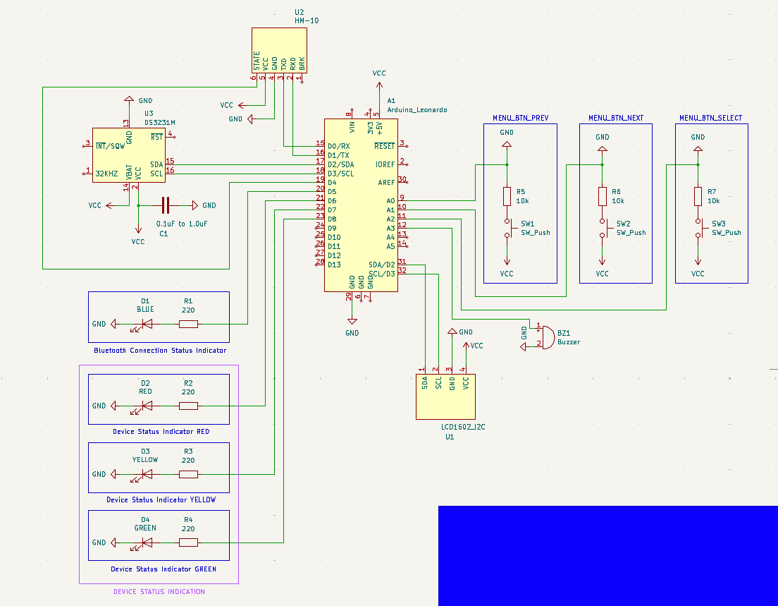
That being said, I would feel more confident if an experienced set of eyes could take a look at my schematic and let me know if anything pops out as wrong/bad practice. Furthermore, with regards to the decoupling capacitor on the DS3231M RTC module (C1 on the schematic) I have a question: Would there be any problem if I use an electrolytic capacitor instead of a ceramic one? I read some stuff about the topic and people recommend using ceramic capacitors most of the time (I think) but others say that there shouldn’t be a problem to use an electrolytic capacitor. I’m asking because I’ve already placed an order for parts, and one of them is this assorted set of electrolytic capacitors.
Please if you notice any mistakes or things that are not done the best way let me know, and try to explain why as simply as you can. As I said, I don’t have a background in EE, even though it highly interests me and I want to learn.
Here is the schematic:
Many thanks in advance!
In parallel. Remember that the parasitic resistance (and inductance) are the major issues.
Capacitance adds in parallel. Resistances / inductances half in parallel. So by putting in parallel the capacitance grows while resistance/inductance shrinks.
“It Depends”. For full details, seek a masters degree in power-electronics, PCB design, power delivery networks, and other advanced subjects.
You’re kinda-sorta on the right track but your understanding of the magnitudes at play here are way off.
https://www.we-online.com/components/products/datasheet/860020672005.pdf
This 1uF aluminum electrolytic capacitor from Wurth Electronics is measured to be 39.553 Ohms. With 2x of this capacitor in parallel you’ll have ~20Ohms (halved) and 2uF of capacitance. (parallel halves the resistance and doubles the capacitance). The 20% to 80% rise-time of RC-circuits can be calculated with just 1.4 * RC constant. This means your two-capacitor team “reacts” within 56 microseconds.
Meanwhile, the 1uF GRT033R60G105ME13 Murata 0201 (American) MLCC / Ceramic capacitor, commonly used for this task, has 0.01 ohms of resistance, roughly a THOUSAND-times less resistance than the Aluminum / Electrolytic capacitor. This capacitor “reacts” to the changing conditions within 0.014 microseconds (aka: 14 nanoseconds).
Do you see the difference? The name of the game is to get:
Enough capacitance to deal with the problem.
After that, minimize resistance as low as possible (and inductance for the “worst” cases, like those 300W GPU we shove into computers), so that the capacitor can actually “react” in time.
Once you “have enough capacitance” (and for most chips, that is 100nF), the way you speed up capacitors is buying low-resistance capacitors. And aluminum is among the slowest / biggest resistance capacitors in the entire market. So they’re a bad choice.
To have your aluminum capacitor team “work” at the same speeds as a ceramic capacitor, you’ll need something like 2000 of them in parallel. Except at that point, you’ll have a lot of other issues with your circuit (see leakage problems, soft-start / load dumps, etc. etc.). Its just the resistance game, Aluminum Electrolytic just fundamentally has too much resistance for this particular job.
Now Aluminum is great for other jobs and other situations. But a big part of your electronics studies from now on is going to be passives (differences between capacitor chemistries, and so forth). No part works like in your textbook. The different chemistries have different reactions at different temperatures, different voltages, different frequencies, different use-cases and more. Its incredibly complicated.
So yeah, seek a Masters-degree for more details. Hopefully this gives you an idea of what one aspect is going through my brain with the above questions.
Thanks for the clarification! As I said, this is my thesis project for my BSc in Computer Science, but I’m definitely considering a more electronics focused masters, especially given the fact I’m already searching for a job in the field of embedded systems/low level stuff. Might be a good piece of paper to have in the future :)