
Hello everyone! First off, I need to mention that my background is in Computer Science (this project is actually for my thesis) and not in Electrical or Computer Engineering. As such, everything I’ve learned has been largely on my own, within the past few months.
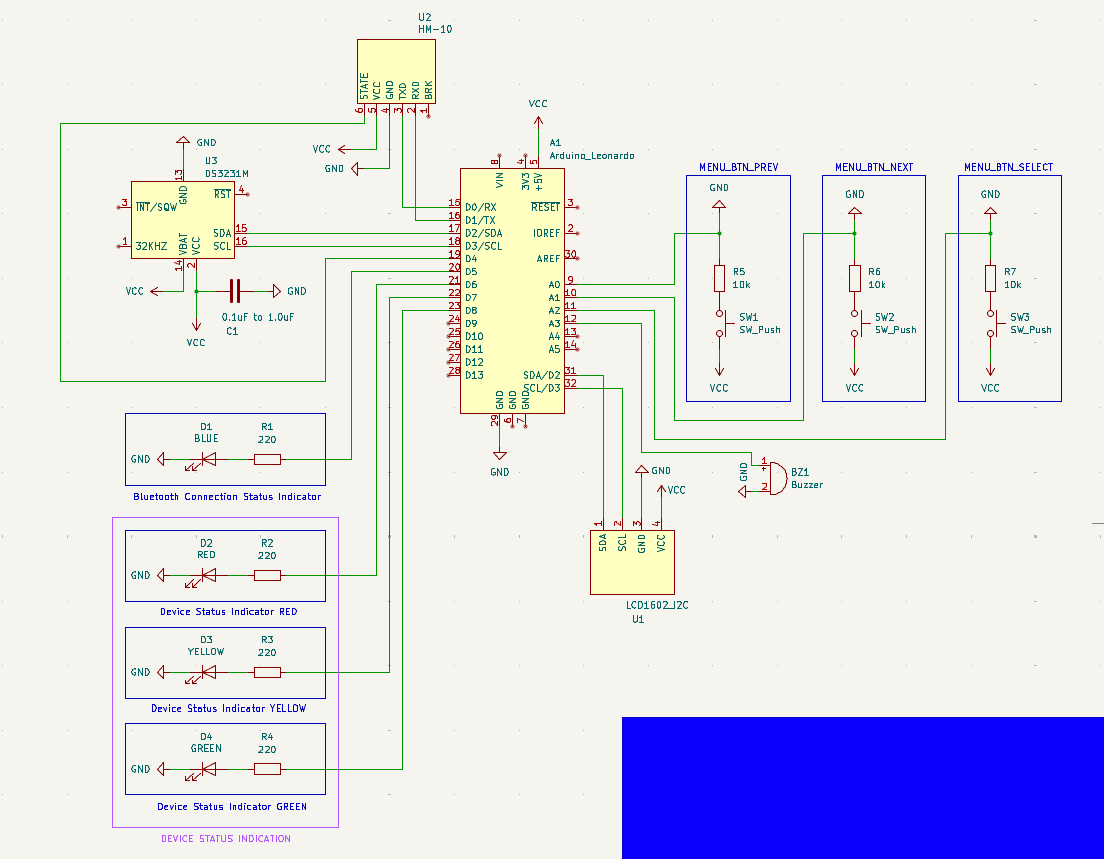
That being said, I would feel more confident if an experienced set of eyes could take a look at my schematic and let me know if anything pops out as wrong/bad practice. Furthermore, with regards to the decoupling capacitor on the DS3231M RTC module (C1 on the schematic) I have a question: Would there be any problem if I use an electrolytic capacitor instead of a ceramic one? I read some stuff about the topic and people recommend using ceramic capacitors most of the time (I think) but others say that there shouldn’t be a problem to use an electrolytic capacitor. I’m asking because I’ve already placed an order for parts, and one of them is this assorted set of electrolytic capacitors.
Please if you notice any mistakes or things that are not done the best way let me know, and try to explain why as simply as you can. As I said, I don’t have a background in EE, even though it highly interests me and I want to learn.
Here is the schematic:
Many thanks in advance!
Thanks, I just submitted a new order for a kit of assorted ceramic capacitors. The comments in this post have been really helpful with regards to the capacitor question, I feel I understand it more now. You people are lovely :)
Honestly it should be a kit of 100nF capacitors. Just 100nF, lol. It’s so ridiculously common.
And 100nF capacitors are like -50% /+100% accurate. Because no one actually cares about their actual capacitance. It’s the decoupling capacitor that’s spammed at somewhat random actual values.
It’s more important to save fractions of a penny and have wide manufacturing tolerances… Rather than care too much about the specific capacitance measured.